How to select an Anti-Vibration Mount - the basics.
How much Static Deflection do I need?
From the blog post "how does vibration absorption work?" we now know that flexibility is key when holding a vibrating machine the next question is “How flexible should it be?”
Before we get into this, there’s a worked example at the bottom of this page, in case you get lost, that should help.
The answer to this “how flexible?” question has to be derived from two pieces of information and a graph. The two pieces of information are:
- What is the forcing frequency we are trying to isolate? For things like generators or pumps, this might be the RPM of the motor, engine or pump. For most applications, there is an obvious answer. However, if you are looking at transport applications, or variable speed applications, things can get complicated. If in doubt, drop us a line to see if we can help you.
- How much do you want to isolate the vibration by? 50 – 90% reduction is a usual target, depending on how problematic the initial vibration is. It goes without saying that, if you want to isolate 90% of the vibration, 10% will be remaining – that’s important later.
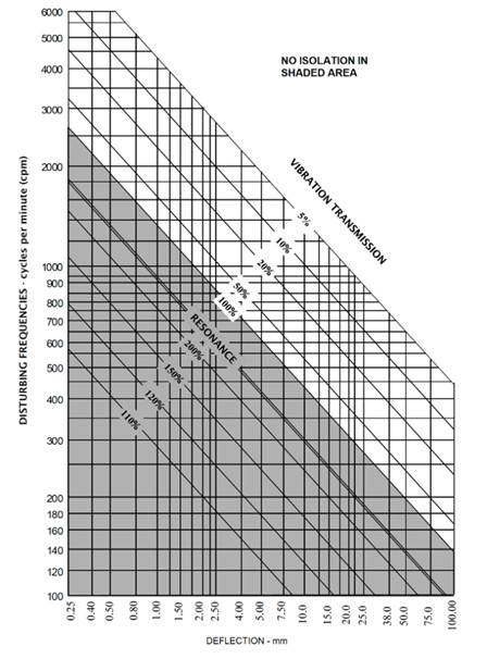
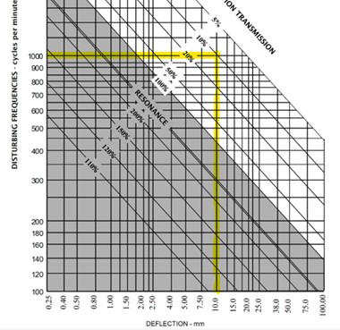
Now that you have this information, use the graph, below, to work out the required deflection. Don’t let this graph intimidate you, it is quite simple once explained:
- Find the “forcing frequency we are trying to isolate” (in cycles/minute) on the left-hand side (Y-axis) of the graph. If in doubt use a lower frequency on the graph.
- Trace across to the right until you meet the relevant diagonal %age line (this is How much vibration energy can remain which you found from answering question 2, above).
- From that point draw a line down to the X-axis, and note the deflection (if in doubt, round up).
This deflection is referring to the difference in height of the mount when the load is applied compared to when it is not applied. This difference is measured when the equipment is switched off and everything is stationary, hence why it is called the ‘static deflection’.
If the mounts were 30mm tall originally, then the load was applied (e.g. the mounts are now supporting the pump) and now they are only 27mm tall, the static deflection is 3mm – the difference between before and after the load is applied.
An example:
Question: I have a pump which spins at 1,000 rpm and is vibrating through the factory floor.  I want to isolate 90% of the vibration, how much deflection do I need in the mounts/feet that I put on it?
Note: The motor might spinning at 3,000 rpm, but through a gearbox, the pump is spinning at 1,000 rpm.  It has been determined that the pump is causing the vibration issue.
You can scroll to the answer below, but you should be able to work out the answer using the information in the question and the isolation graph.
Nearly there…
Answer: After finding the 1,000 cycles per minute line on the left-hand side, I tracked across to the 10% (remaining) line (see yellow highlighted line on graph), which represents 90% isolation. From there I went down to the X-axis to find that I require 10mm of static deflection on each foot of my pump.
So, the answer is 10mm of static deflection to isolate 90% of the vibration caused at 1,000rpm.
What do I do with this Information?
Ok, so hopefully you are now comfortable with the basics of how to establish the amount of deflection you require.
What do we now do with this information? The answer is nothing – yet. We need one other piece of information first – the load each AV mount will carry.
This is normally an easy step. Once we understand the static deflection requirements, we need to look at the load we are trying to isolate on each mounting point (or foot).
Key questions:
To understand the load per mount, we need to understand:
- How heavy is the equipment we are isolating?
- Use the max load incl. any fuels, pipework etc that can increase the supported weight. We have seen overloaded mounts due to the shipped or dry weight being used.
- How many feet does it have?
- Is the centre of gravity evenly positioned over the feet (so, is the load evenly distributed)? If not, we need to take some moments to calculate the loads per foot. This is not tricky, but I will cover it separately. For now, let’s assume loads are evenly distributed as they are for most of our day-to-day enquiries.
From this, we can work out how much load is on each foot or mount.
Why does load matter?
Well, there are a few reasons:
- Mounts have a working range.
- If you overload a rubber mount the worst-case scenario is tearing, failure and/or collapse. At a minimum the mount will be less effective at its job as when an AV mount is over compressed it ‘bottoms out’ and becomes solid, which prevents it from isolating.
- If your mount is insufficiently loaded it won’t do its job either – it might not deflect enough resulting in reduced isolation and potentially resonance.
- We want all the mounts to have a similar level of deflection to avoid an imbalance in the natural frequency of the system we are generating. We will talk more about this in another post.
So, we need to know that the load will sit in the AV mount’s “goldilocks zone”:
- Not too much load to avoid overloading
- Not too little load to work the mount properly and to avoid the risk of resonance.
For simplicity, assume our pump from the example in “Part 2: Static Deflection” weighs 1,000 kgs, and that weight is supported evenly by 4 feet, so 250kg/foot.
Select the right Mount
Now that we have our desired deflection and our load per foot, it is time to find products which fit the bill. There are plenty on our shop at AVMR.com
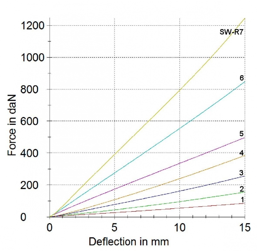
Well tested AV mounts will normally be specified with deflection graphs, like the one below, for our SW-R mounts:
 |
 |
|
AVMR’s SW-R Sandwich Mount range: compression data and image Note: 1 daN is broadly equivalent to 1kg |
|
This graph has a series of deflection lines which show how much each variant deflects with load. This will normally be given in partnership with the maximum suggested loads for the product.
We have decided that AVMR’s SW-R range of products is right for our application, so want to find a variant which deflects around 10mm under 250kg (or circa 250daN)
Looking at the variants available, we can see that the following options are closest:

SW-R mount compression data (excuse the wobbly ‘blue peter’ lines drawn)
- SW-R3 will deflect circa 14mm*
- SW-R4 will deflect circa 10mm
- SW-R5 will deflect circa 7mm
When the anticipated deflections are taken from the product deflection graph, this can be reviewed in the Isolation Graph from Part 2 and isolation levels predicted (see info in brackets, below).
- SW-R3 will give 90-95% isolation*
- SW-R4 will give 90% isolation
- SW-R5 will give 80-90% isolation
SW-R4 gives us exactly what we were looking for, while options 3 and 5 are close. We could push to increase the isolation with SW-R5, or reduce work that the mount has to conduct and go for SW-R3. The ultimate decision depends on overall requirements and priorities.
